When M9381A is connected, you will see the display as below:
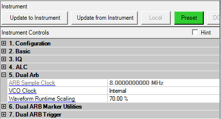
Range: Depends on the connected instrument.
The sampling clock frequency of the signal generator is automatically calculated by the software application.
This parameter is not available with all instrument model numbers and may be grayed out.
VCO Clock is enabled with M9381A.
Choice: Internal | External
Default: Internal
Double-click or use the drop-down menu to select the signal generator’s VCO Clock.
Internal − the signal generator uses its internal VCO Clock.
External − the signal generator uses an external VCO Clock.
Range: 1% to 100%
Default: 70%
Use this cell after downloading and synchronizing with the signal generator.
Use this parameter to reduce the overshoot associated with the digital-to-analog convertor (DAC) interpolation filter. Enter a scaling value for the signal generator to apply to the waveform while it is playing. Use scaling to get the best dynamic range without overflowing the I and Q digital to analog converters. At 100 percent, some overshoot may occur; therefore the default setting is 70 percent.
This parameter is not available with all instrument model numbers and may be grayed out.
Choice: Auto | 2.1 MHz | 40 MHz | Through
Default: Auto
Use this cell after downloading and synchronizing with the signal generator.
Use this cell to select a filter for I/Q signals modulated onto the RF carrier. The bandwidth of the baseband signal should dictate the minimum reconstruction filter bandwidth you choose. Depending on the oversampling ratio and where the image frequencies appear, you may want to select a wider bandwidth.
Auto − automatically selects a digital modulation filter.
2.1 MHz − applies a 2.1 MHz baseband filter to the I/Q signals.
40 MHz − applies a 40 MHz baseband filter to the I/Q signals.
Through − bypasses filtering.
This parameter is not available with all instrument model numbers and may be grayed out.
Choice: Auto | 40 MHz | Through
Default: Auto
Use this cell after downloading and synchronizing with the signal generator.
Use this cell to select a filter or through path for routing I and Q signals to the rear panel I/Q outputs.
Auto − automatically selects an I/Q output filter.
40 MHz − applies a 40 MHz baseband filter.
Through − bypasses filtering.
Choice: Auto | Manual
Default: Auto
Use this cell after downloading and synchronizing with the signal generator.
Select the mode of the internal I/Q modulator.
Manual − manually set the attenuation level of the I/Q modulator using the Modulation Attenuation cell.
Auto − the attenuation level automatically sets to a value for best performance based on the digital modulation settings.
Range: 0.00 to 40.00 dB
Default: 10.00 dB
Set to to enable this parameter.
Set the attenuation of the I/Q signals being modulated through the signal generator RF path. Adjusting the attenuation may reduce signal distortion and improve the overall dynamic range.
This parameter is not available with all instrument model numbers and may be grayed out.
Choice: On | Off
Default: On
Use this cell after downloading and synchronizing with the signal generator.
Double-click or use the drop-down menu to enable or disable the signal generator’s high crest mode.
On − processes high-crest-factor arbitrary I/Q waveforms with less distortion. For crest factors higher than 4 dB, you should reduce I/Q Modulation Attenuation levels by 1 dB for each dB above that level. High crest mode reduces the maximum output level and degrades power level accuracy.
Off − disables the high crest mode.
Choice: Internal | External
Default: Internal
This parameter is not available with all instrument model numbers and may be grayed out.
Use this cell after downloading and synchronizing with the signal generator.
Double-click or use the drop-down menu to select the signal generator’s ARB reference source .
Internal − the signal generator uses its internally generated 10 MHz signal as the reference source.
External − the signal generator uses an external signal as the reference frequency for the baseband I/Q signal. Connect to the rear-panel BASEBAND GEN REF IN connector. See the signal generator’s User’s Guide for information on external references.
This parameter is not available with all instrument model numbers and may be grayed out.
Range: 0.2500000 to 100.0000000 MHz
Default: 10.0000000 MHz
Set to to enable this parameter.
Use this cell after downloading and synchronizing with the signal generator.
Enter the frequency value of the external reference when using an externally supplied reference signal. See the signal generator’s User’s Guide for information on external references.